How to Find a Projection Matrix: The First Step
Grades 11-12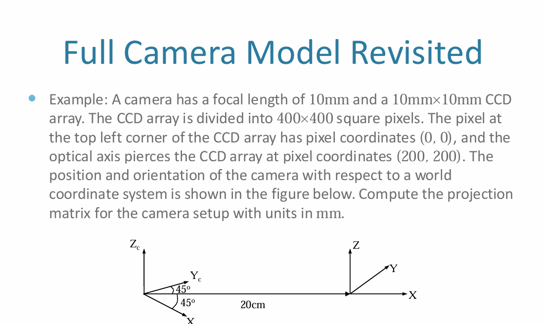
Question: explain what is the first step that I should find? for the projection matrix
To find the projection matrix for a camera, the first step is to establish the Intrinsic Matrix, often denoted as
. This matrix describes the internal geometric properties of the camera—essentially, how it converts 3D coordinates in the camera's view into 2D pixel coordinates on the sensor.
To calculate this matrix, you need to synthesize the hardware specifications provided in the text:
- Focal Length in Pixels: The focal length is given as . However, the matrix requires this value in "pixel units." You find this by multiplying the physical focal length by the pixel density (pixels per mm). Since a sensor is divided into pixels, the density is . Thus, the focal length in pixels ( and ) is:
- Principal Point: This is the pixel coordinate where the optical axis (the center of the lens's view) hits the sensor. The problem states this occurs at . These are your and values.
- The Matrix Structure: The resulting Intrinsic Matrix takes the form:
Once this is established, the next logical step is to determine the Extrinsic Parameters, which involve the Rotation (
) and Translation (
) shown in your diagram. This defines where the camera is located in the world and how it is tilted.
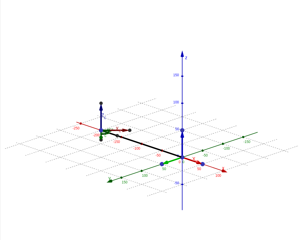
Visualizing the Setup
In the 3D model below:
- The World Coordinate System is shown at the origin on the right. The -axis is red, is green, and is blue.
- The Camera Coordinate System is located away on the left.
- Note the rotation: The camera's and axes are rotated relative to the world's -axis, while the axis remains parallel to the world's -axis.
- The Translation vector represents the position of the world origin relative to the camera's center.
Drawing these two frames clearly is essential for deriving the Rotation matrix
and the Translation vector
used in the final projection formula
.